1. Introduction & Circuit Analogy
Electrophysiology is generally used to monitor the transport rates of ions across membranes through ion channels, where the rate of transport is measured as an ionic current (in picoamps, pA). This phenomenon arises simply because ions carry charges, and potentials, or voltages (in millivolts, mV), can be applied across membranes.
These potentials are called membrane potentials (Vm or Δψ), and they are created either electrically (e.g., by a battery with electrodes on either side of the membrane) or chemically by asymmetric solutions of ions (recalling the Nernst equation).
The Biological Circuit
An interesting analogy can be drawn between biological ion channels and electronic circuits. The ion channel acts as a resistor (Rm) [Gigaohms (GΩ)], or inversely, as a conductor (ρm = Rm-1) [picosiemens (pS)]. The phospholipid bilayer acts as a capacitor (Cm).
2. The Basic Rig
Single-channel recordings deepen our understanding of channel function, helping to elucidate mechanisms of membrane transport. While patch clamping is a typical approach allowing the study of channels in native surroundings, Planar Lipid Bilayer (BLM) electrophysiology provides distinct advantages: absolute control of the constituents on either side of the membrane, manipulation of lipid composition, and the ability to study challenging channels inaccessible to patch-clamp.
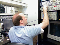
The Amplifier
We utilize Axopatch 200B voltage-clamp amplifiers. They are capable of low-noise recordings in single-channel mode and interface directly with the custom bilayer cell inside the Faraday cage.
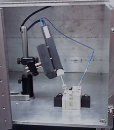
The Bilayer Cell
Inside the sturdy metal Faraday cage (which blocks sound vibrations and AC electrical noise) sits the bilayer cell. It contains cis and trans chambers connected to the headstage via Ag/AgCl electrodes.
3. The Capacitance Test
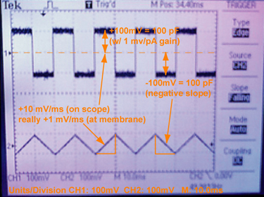
The capacitance test is the practical means of determining the size and quality of an artificial bilayer membrane. A capacitor stores charges of opposite sign within conductive plates on either side of a dielectric medium. A phospholipid bilayer represents this exactly.
For a pair of parallel disk conductors (radius r), the capacity is directly proportional to the area and the permittivity (ε), and inversely proportional to the thickness (d):
A phospholipid membrane has a capacitance per unit area of roughly 1 μF/cm². Thus, a 200 μm hole has a theoretical maximum of ~300 pF. In reality, it is hard to achieve this ideal number due to the thick torus (Plateau-Gibbs border) of amorphous lipid surrounding the thinned bilayer.
The Triangle Wave Derivative
To measure this, we apply a symmetric triangle wave voltage function (V), where the rate of change is a constant (e.g., ±1 V/s). The relationship between charge (q), voltage (V), and capacitance (C) is C = q / V. Taking the time-dependent derivative:
Because dV/dt is a constant during a triangle wave, the resulting instantaneous current (i) is a square wave. One-half of the peak-to-peak output of this square wave is equal to the membrane's capacitance. (You can visualize this mathematically in the Simulator below).
4. Laboratory Protocols
Salt Bridges
Make a 2% agarose solution in 3 M KCl using a microwave, kept liquid at ~95°C. Using a luer adapter, draw hot agar slowly through 0.06 in. O.D. polyethylene (PE) tubing (to avoid bubbles). (BD Intramedic P/N is 427426.) After solidifying, cut into 10-cm bridges and store in 3 M KCl.
Lipid Solution (DPhPC/decane)
Dry DPhPC (1,2-diphytanoyl-sn-glycerol-3-phosphocholine) from chloroform under a dry nitrogen stream thoroughly (at least 30 mins after last traces vanish). Resuspend in n-decane to 30 mg/ml. It may take hours to a day to fully resuspend.
Folch Solution
A 2:1 ratio solution of chloroform and methanol. Used to separate nonpolar lipids from polar proteins, and to clean paint brushes/tubes. Named after the prominent neurochemist Jordi Folch-Pi (1911-1979).
Forming a Membrane
Paint the area around the hole on either side with lipid solution and let dry. Bathe both sides in aqueous buffer. Turn on the triangle-wave generator. Re-dip the brush and gently wipe the bristles over the hole until a conductance-blocking seal forms and capacitance rises. Thin the membrane by passing an air bubble over the hole; air bubble is made via a simple closed-end tubing tool. Monitor progress of membrane with empirically optimal capacitance reading for hole size.
Clean-up
Remove cell from holder and clean it thoroughly using 50 mM phosphate tribasic (pH 12) to help remove lipids and proteins. Follow that with distilled water and an ethanol rinse for dying under an air stream.